In this third post related to Computational Fluid Dynamics (CFD) we will look at a classic example of transient analysis: vortex shedding in the wake of a cylinder. We will again use Acusolve solver with its pre-processor, Hyperworks CFD.
We are going to study the flow around a cylinder with a Reynolds number close to 100 at the inlet. This problem has been studied on numerous occasions, and it is known that for Reynolds number values around 100, the flow releases a series of vortices as it passes through the cylinder in conditions of unsteady laminar flow.
The aim of the simulation will be to visualise these vortices and their temporal evolution. The steps to follow are detailed in the tutorial available in our Downloads section, in this post we will see the most important aspects to take into account.
Model geometry
First, the geometrical model is defined. It is important to ensure that there is enough space in all directions around the cylinder so that the boundary conditions do not affect the flow to be studied. In this example the model is, for practical purposes, two-dimensional. Acusolve requires working with a three-dimensional model, so we give the domain a thickness similar to the element size to be used in the area of low interest. The simulation domain is shown in the following image.

As domain material, for this study we will use a manually defined material with 1 kg/m3 density and 0.01 Pa-s dynamic viscosity. Thus, imposing an inlet velocity of 1m/s, the Reynolds number at the inlet is equal to 100. Symmetry conditions are placed on the side faces to reflect the two-dimensionality sought.
CFD model meshing
For the mesh, an element size similar to the thickness is used in the regions of low interest. As refinement zones, two 5-metre wide bands centred on the cylinder are defined as shown in the image.

The tutorial also shows a useful process in this type of study, in which the transient CFD simulation is given the result of a related stationary analysis as an initial condition. In this way, the desired flow instabilities are directly observed in the simulation, without going through a first stage in which the flow progressively reaches the cylinder. This tutorial also explains how to modify the Acusolve .inp file and launch simulations from the terminal.
CFD Simulation: Vortex shedding
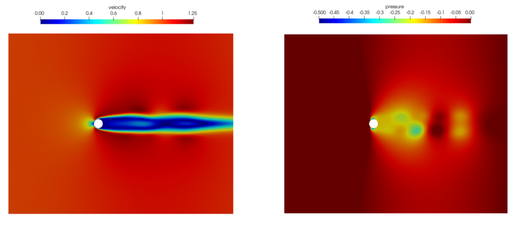
Finally, some simulation results are presented, which show the vortex shedding from a laminar flow situation. The results of velocity and pressure in the wake of the cylinder at the final instant of the simulation are given in the image. The Hyperworks CFD animation with the Post-Processing tool allows to see the evolution.

In the next post we will see an example of a multiphase simulation using the LES turbulence model. Specifically, we will use the NIST Fire Dynamics Simulator (FDS) software to simulate a garage fire and the efficiency of smoke extraction. We will explain the process from the preparation of the model to the post-processing of the results with Smokeview.


