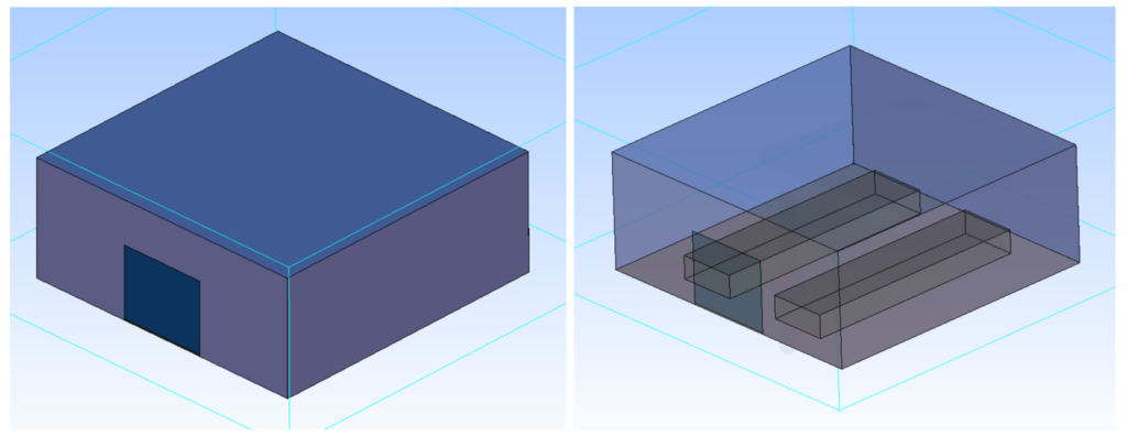
In this post we will show an example of a simulation of an HVAC system using Computational Fluid Dynamics (CFD). In the example we will analyse an enclosure with some internal elements, as can be seen in the image. We will compare a fan heater system with an underfloor heating system. We will show the main aspects to take into account from our experience in HVAC simulation.
This post will be followed by a more detailed tutorial in our Downloads section where you can see the steps to follow in Cradle ScStream software.
CFD model preparation
After importing the geometry, the next step is to assign the materials to the enclosures and objects. In the case of solids, it is sufficient to assign the material from the Cradle library, since all the thermal properties are already described there. For panel type elements a thickness must be assigned for thermal purposes. This option maintains the accuracy of the thermal study while reducing the number of elements and improving the calculation speed.
To take into account the convection with the outside, the domain has been extended beyond the walls. For the side and top borders the air is set to enter at 10oC. A constant temperature condition is placed on the ground, which may differ from that of the outside air.
For the meshing in this type of simulations, it is convenient to define an inner area inside the ship where we take a fine element size and an outer area with a coarser mesh as shown in the following image. In total, about 500,000 elements are used for this example.

Definition of HVAC systems
In the case of underfloor heating, starting from the panel element, we can set the power in W/m2 or set a fixed temperature corresponding to the operation of the system. Depending on the available manufacturer’s data, one or the other can be chosen.
For fan heaters, the geometries are defined and the air inlet and air intake surfaces are assigned. In this case we have placed the supply air horizontal, but it could be changed without any problem to give it an angle without modifying the geometry. This system is shown in the following image.

CFD Simulation and Results
The best indicator that steady state has been reached in these simulations is the average temperature inside the ship. This must be analysed together with other numerical indicators to accept a simulation as valid.
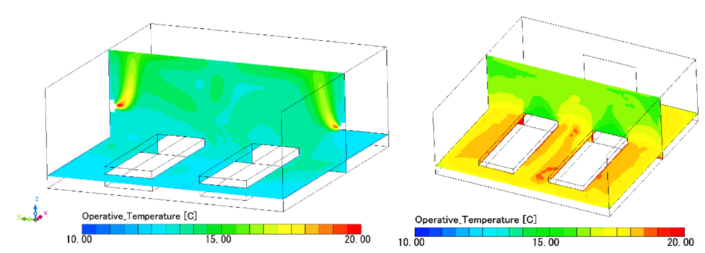
Once the simulation has been completed, result maps can be obtained for a large number of variables related to the energy efficiency of the systems and the thermal comfort provided by the alternatives. As an example, we will show the operating temperature and the Predicted Mean Vote in two representative planes.
On the left we see the results of the fan heater system and on the right the results of the underfloor heating system first for the temperature.
And then for the Predicted Mean Vote (PMV):
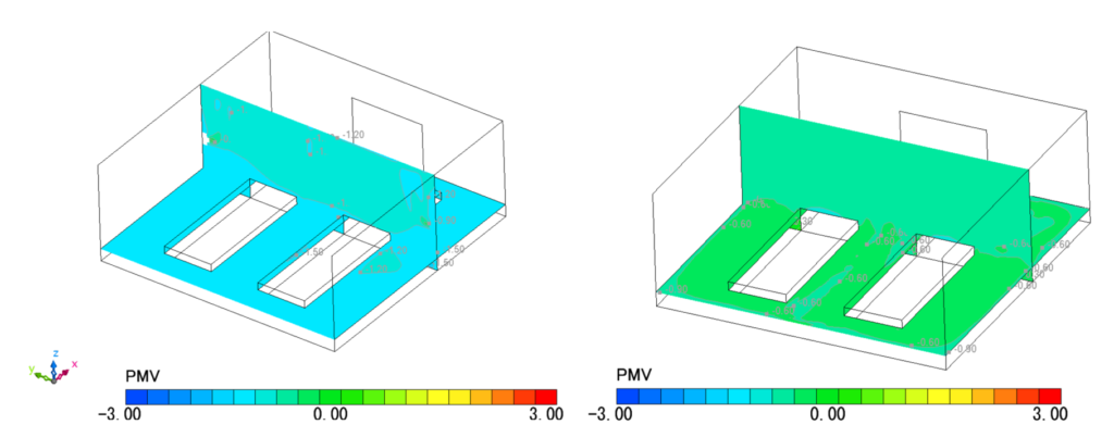
Through the HVAC simulation it can be concluded that the underfloor heating system is a better alternative for thermal comfort purposes with the powers considered for each proposal.
In later stages of an air-conditioning study, the causes of this difference should be analysed and modifications to the sized equipment should be proposed. At the end of the optimisation stages, the economic and efficiency aspects of the alternatives should also be assessed, and the information obtained will allow a better decision to be made as to which system is the most suitable.