The aim of this project is to simulate and validate a new design for a large industrial biomass gasifier. The improvement aims to facilitate the operation of some parts of the process and requires a relevant modification of the air introduction and bed fluidisation system. The calculation project includes several phases that are detailed in this entry.
Air Distributor Optimisation with CFD Simulation
Firstly, a CFD simulation study of the air distributor is carried out. The system’s pressure losses and the flow rates provided by each outlet are calculated. To do this, the geometry is meshed considering a suitable boundary layer and, after configuring the model, the calculation is carried out using Cradle ScFlow. The following image shows a detail of the mesh used in one of the zones of the system:

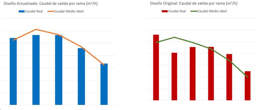
After an initial analysis, possible improvements to make the flow more uniform and improve consumption are studied. These proposals are aimed at facilitating the flow through the distributor, smoothing the turns and thereby reducing secondary losses. The following image shows a comparative graph of flow rates before and after the optimisation process, where the improvement in homogeneity of the distribution sectors can be seen:
CFD simulation of these cases allows comparison of efficiency at early design stages, before construction of the equipment begins.
Study and calibration using a laboratory model
The second phase of the study is a calibration of the numerical drag models to represent fluidisation.
The starting point is a model corresponding to a laboratory experiment for which measurements of fluidisation heights and minimum velocities are available. Once the physical parameters of the particles and the numerical parameters for the entrainment model have been calibrated, a sensitivity study is carried out on the parameters that vary with respect to the real reactor.
Some of the parameters considered are vessel diameter, bed height and flow velocity. Using intermediate models, it is possible to define an appropriate methodology to work with the real reactor model using CFD-PIC type simulation, coupling the flow and solid particle entrainment phenomena.
A study of the flow velocity causing pneumatic drag in the fluidised bed is also carried out at this stage, providing design-relevant data that would be quite costly to verify experimentally.
Multiphase simulation of the reactors
In this phase, the calibration results are used to simulate the reactor in its current configuration and the new designs. The simulation of the already built and operating model serves as a validation of the process used.
Once the results of this study have been validated, the new designs are studied. In these, the phenomena of adequate fluidisation and maximum bed height are studied. The results obtained provide greater confidence in the modification proposals.
The following videos show animations of the results of some fluidisation simulations in different configurations:
DEM Simulation of the metal Extraction System
Finally, a study is carried out on the process of extracting the unwanted waste generated by biomass gasification. The aim of this study is to check that the design of the extractor screw allows the gasifier to work properly, without accumulations of materials that penalise efficiency.
This study is carried out by means of DEM (Discrete element method) simulation with Coarse Grain Model without fluid-particle interaction. This allows to greatly increase the efficiency of the calculation while maintaining a good accuracy in the results.
The following video shows an example of the study in a certain configuration of those considered in the process:
These studies and their subsequent analysis conclude the multiphysics simulation part of the project.
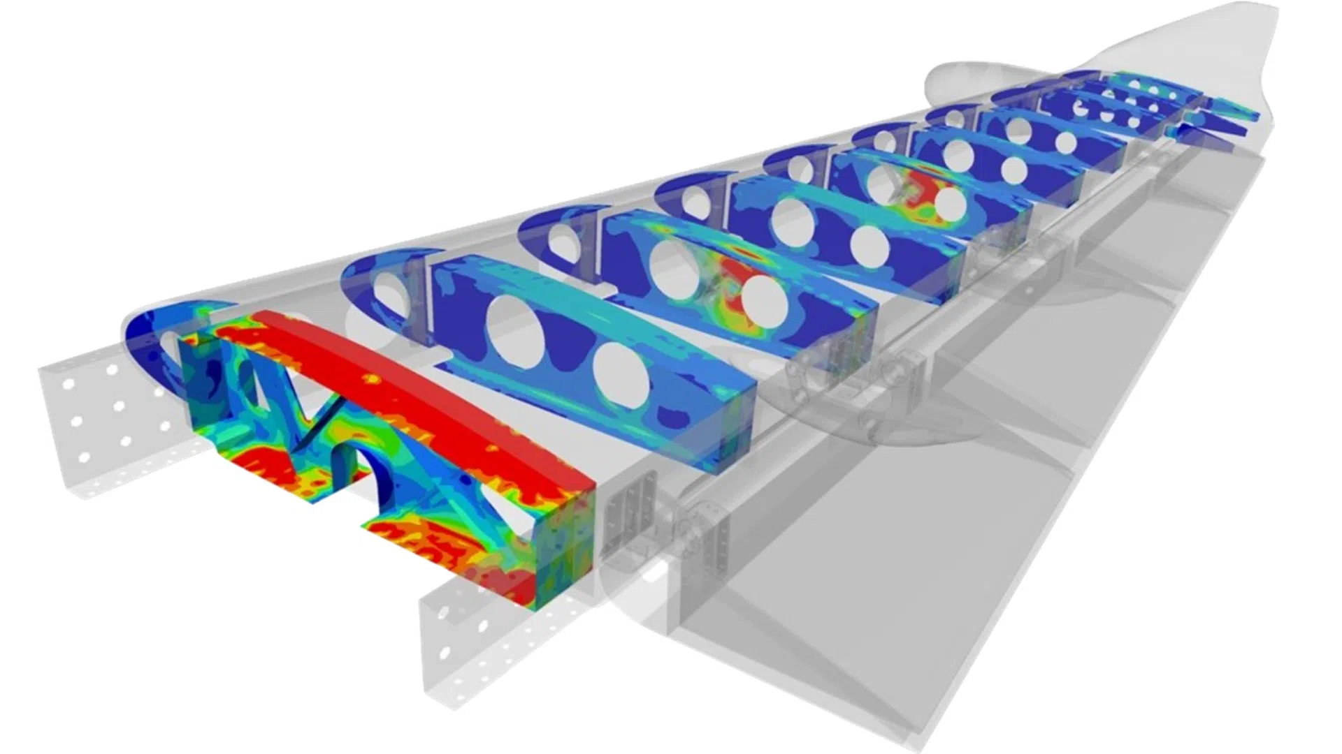
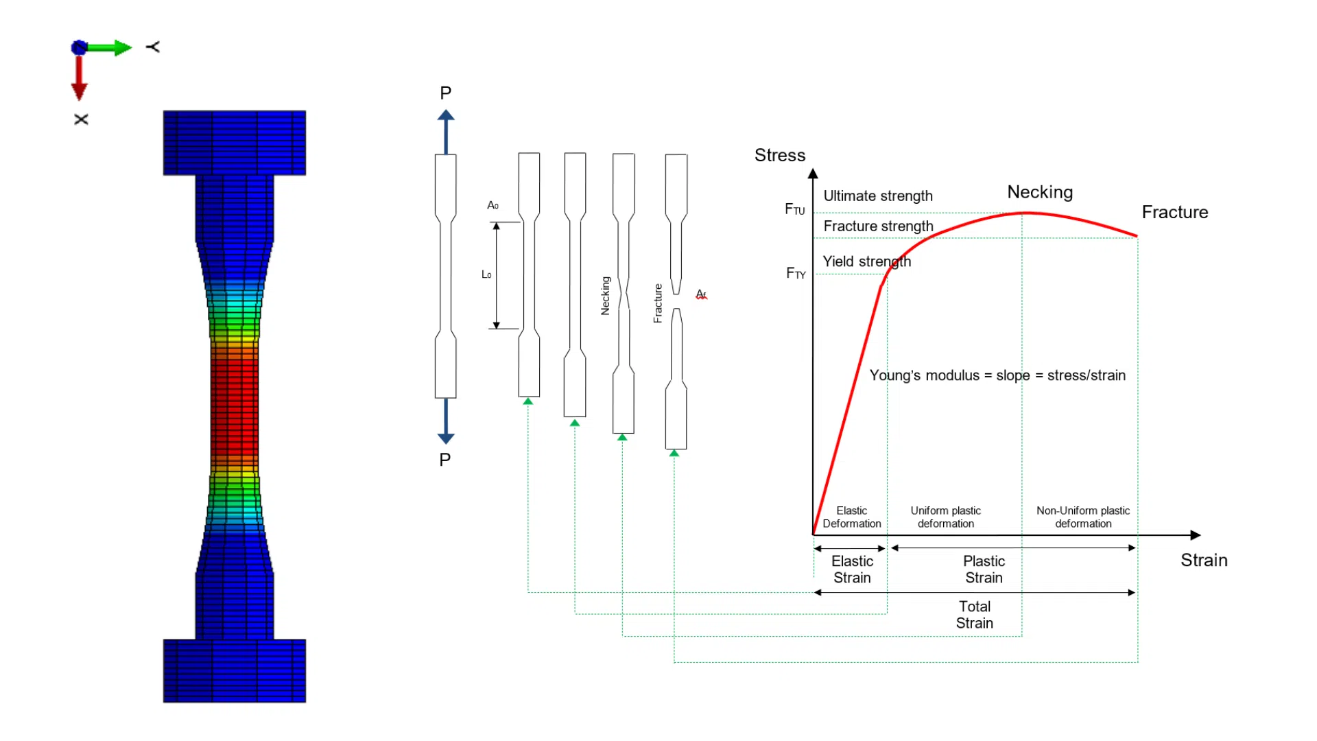
In addition to what is mentioned in this entry, ICEMM also carried out a structural strength analysis of the new design using Finite Element models, thus verifying the reactor’s compliance with the applicable regulations in this field.